n:w explains
April 1, 2021

BIM and digital design: A closer look at how mass timber goes from factory to building site

Early daytime construction aerial view of Brock Commons Tallwood House showing completed central elevator shafts protruding above cross-laminated timber (CLT) floor panels being set in place
Brock Commons Tallwood House at The University of British Columbia | Photo credit: KK Law

By Eduardo Souza, ArchDaily

Le Corbusier’s fascination with the automobile is evident in the architect’s various photographic records of him posing proudly next to a car in front of his architectural work. According to the Franco-Swiss architect, in addition to enabling more efficient and economical construction, the industrialization of architecture could form the basis of improved aesthetic results in the same way the modern car chassis supports the creative and modern design of the automobile body.

Yet, while vehicles have experienced impressive changes since the 1930s, it can be said that architecture has been slower to adopt the advances of other industries.

But that has been changing little by little. Driven by concerns around sustainability, the use of non-renewable fossil resources, and efficiency, coupled with accelerating demand to build new buildings and more accessible infrastructure, the construction industry has been incorporating numerous new technologies, including those adopted from other industries. In addition, renewable materials such as wood have been identified as an ideal construction material—especially when incorporating innovative mass timber products such as CLT and glulam, design methods and processes like BIM and DfMA, tools for visualization such as VDC, and tools for manufacturing such as CNC. We know, these are a lot of acronyms, but we will try to clarify them throughout this article.

What is design for manufacture and assembly (DfMA)?

Design for manufacture and assembly (DfMA) is a design approach that focuses on both ease of manufacturing for the product parts and the simplified assembly of the final product. It combines two methodologies; design for manufacture and design for assembly. That is, from the initial stages of creation, decisions are based on avoiding problems during construction and improving efficiency.

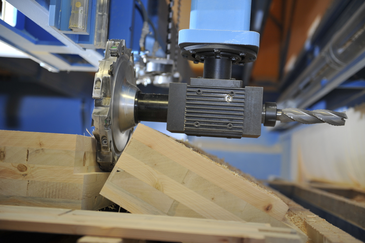
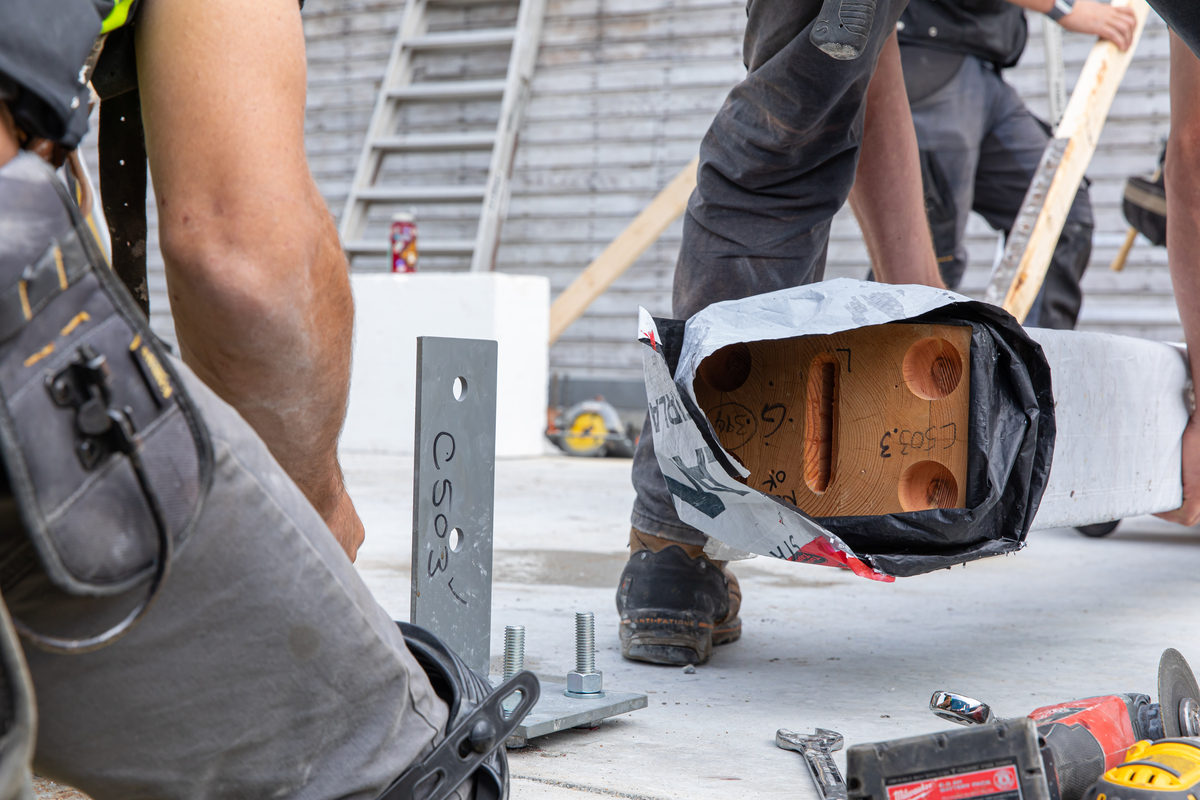
This is an approach used across many industries, and in construction, it is particularly well suited for mass timber using products like cross-laminated timber (CLT) or glue-laminated timber (glulam). This is because, when designing and building with mass timber, the construction itself is much more an assembly of parts, and is quite different from the design and construction of more traditional construction. Mass timber panels, beams and columns are manufactured offsite and transported to the construction site, prefabricated with all the stops and holes for accommodating the predefined installations, including MEP (mechanical, electrical, and plumbing). For the process to be smooth from beginning to end, it is essential to organize starting from the initial stages of the project, allowing diverse teams to connect early on to contribute to the final product, avoiding delays and setbacks at the construction site. It is at this point that building information modelling (BIM) helps a lot in the process.

Off-site prefabrication of CLT panels. | Photo credit: Swanky Photography

CLT production Swanky courtesy naturally wood

What is building information modelling (BIM)?

BIM refers to a set of technologies, processes, and policies that allow various stakeholders to collaboratively design, build, and operate an installation in the virtual space, forming a reliable basis for decisions throughout the life cycle of the building, from first ideas to demolition. In other words, for any project to flow efficiently, it is important that everyone speaks the same language—BIM.

It allows for the visualization and simulation of all parts of a work, providing an understanding of the assembly and feasibility of modelled solutions. It also supports a shared understanding of the design solution through the 3D model, which can facilitate cooperation among the project team and eliminates the risk of common errors in the interpretation of 2D drawings. Combined with this, the model can be exported to several other programs for structural and thermal analysis, and can also generate files for machining by computer numeric control (CNC) machines.

1 Lonsdale Avenue (formerly PH1) construction. |  Photo credit: KK Law


PH1 construction prefabrication mass timber naturallywood